Procedural Terrain Generation Using Perlin Noise
Procedural Terrain Generation Using Perlin Noise
GitHub: https://github.com/hmxsqaq/Unity-ProceduralMapGenerationPerlinNoise
Foreword
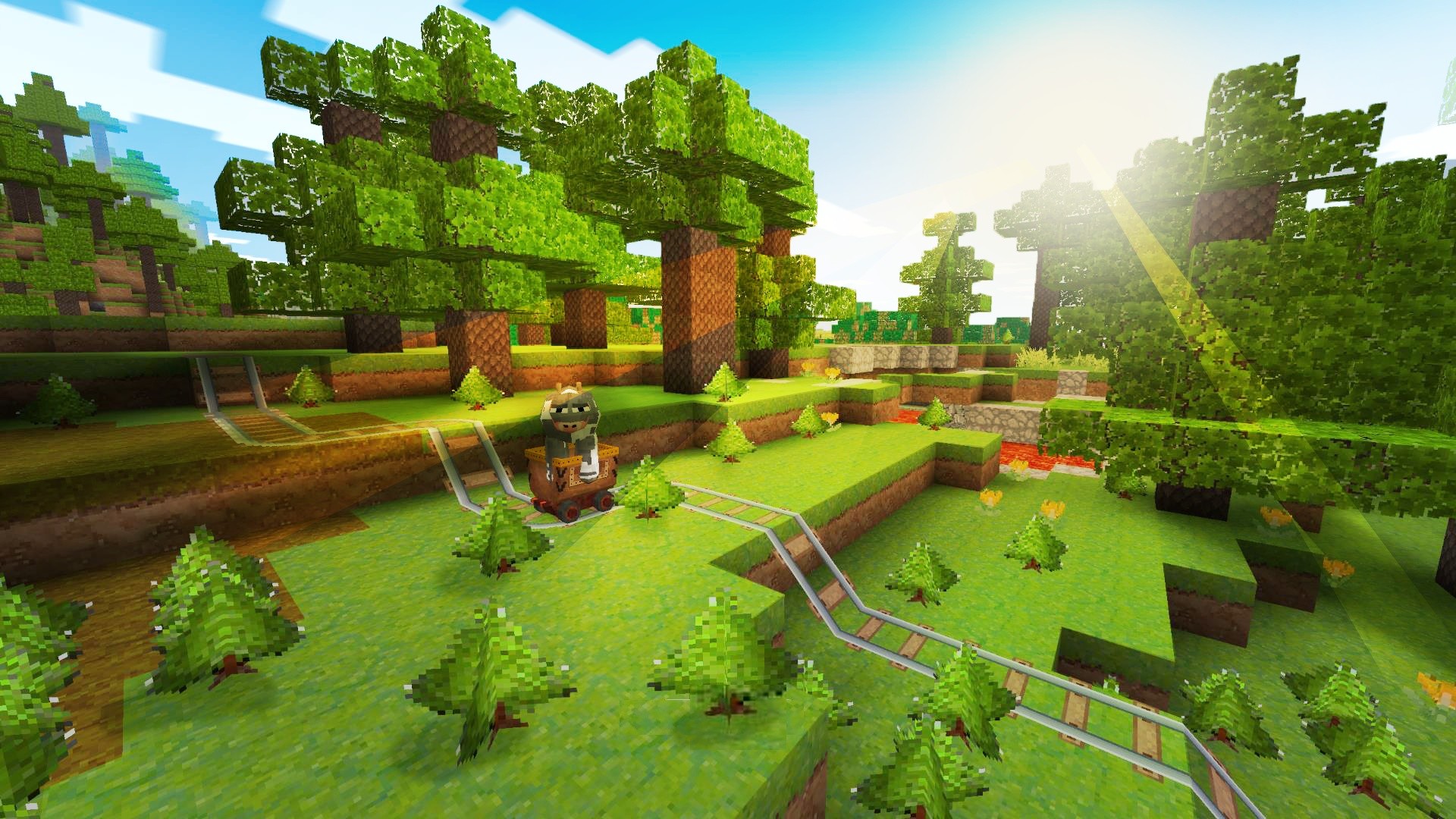
With the rapid advancement of computer graphics, Procedural Generation (PG) has become increasingly widespread in game development. From Minecraft and the Civilization series to various Roguelike games, PG has demonstrated immense potential and infinite possibilities. It significantly liberates productivity, freeing artists from tedious scene editing, and provides unparalleled replay value by ensuring every “new game” is full of surprises.
Among the many procedural generation techniques, the Perlin Noise algorithm, proposed by Ken Perlin in 1983, is highly favored for its ability to generate smooth, natural-looking noise images. Its characteristic smooth transitions make it exceptionally well-suited for simulating natural phenomena and generating terrain and textures. The enduringly popular sandbox game Minecraft heavily utilizes Perlin noise in its map generation algorithms.
This article aims to explore the principles, implementation, and practical applications of the Perlin noise algorithm from a beginner’s point of view. I will use the Unity game engine and the C# language to implement the algorithm and apply it to practical procedural generation tasks, such as creating 2D Tilemap worlds and 3D mountainous terrain. Furthermore, to enhance the generation results, this article will delve into advanced applications and optimizations of Perlin noise, such as Fractal Perlin Noise and erosion algorithms. To provide a more comprehensive overview of procedural generation, other common algorithms like Simplex Noise and Diffusion-Limited Aggregation (DLA) will also be briefly introduced.
Through this exploration, I aim to develop a holistic understanding of procedural generation technology and the implementation of its core techniques and algorithms.
What is Perlin Noise?
Overview
In programming, we often use functions like rand() to generate random values. However, this simple randomness is often too “random,” producing chaotic and disjointed results. Our world isn’t like that; mountains and rivers have natural flows and gradients. When we need to generate random terrain or similar features, simple randomness falls short. In computer graphics, noise can be described as a random signal. By using specific noise algorithms, we can obtain signals that are random yet smoothly transitional.
Perlin Noise is, as its name suggests, a type of noise. It is a noise generation algorithm that produces continuous, smooth, and hashable (deterministic) random values, avoiding the sharp boundaries and unnatural transitions common in traditional random functions. It was invented by Ken Perlin in 1983, initially for creating special effects in the movie Tron, and won an Academy Award for Technical Achievement in 1997 (not 1985).
Perlin noise has two critically important properties:
- Continuity: For continuous inputs, the returned random noise values are also continuous.
- Determinism (Hashable): For the same input, the output is always the same.
These two properties give Perlin noise unparalleled flexibility and versatility.
Principle
The core idea behind implementing Perlin noise is actually not complex: achieve smooth transitions by interpolating gradients. Here are the specific steps:
- Define a Grid and Assign Gradients In a given dimensional space, define a grid at fixed intervals. Assign a random gradient vector to each grid point according to a set rule.
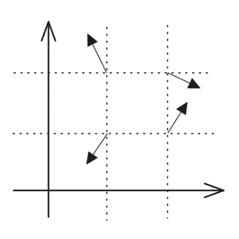
- Calculate the Grid Cell for a Given Point For any given point, determine the grid cell it belongs to. In 2D space, this means finding the four surrounding grid points and the distance vectors from each of these grid points to the given point.
-
Calculate Influence Values For each surrounding grid point, calculate the dot product of its gradient vector and the distance vector from step 2. This dot product represents the “influence” of that grid point on the final value.
-
Interpolate to Get the Noise Value Use an interpolation function, such as bilinear interpolation for a 2D plane, to combine the influence values. The result is the final noise value for the given point.
Perlin Noise Algorithm Implementation
In the previous section, I briefly introduced the principles of Perlin noise. While it may not seem difficult, there are many important details in its implementation. Based on Ken Perlin’s paper “Improving Noise” from SIGGRAPH 2002, I have implemented a C# version of the Perlin noise algorithm in Unity:
Note: Unity’s Mathf library provides a built-in method for Perlin noise. This implementation is for a better understanding of the algorithm. For practical applications, using the library function is sufficient.
In my version, I implemented Perlin noise for both 2D and 3D space. The fundamental logic is similar. Below is a detailed explanation of the 2D implementation:
- Permutation Table
private static readonly List<int> Permutation256 = new(256)
{
    151, 160, 137, 91, 90, 15, 131, 13, 201, 95, 96, 53, 194, 233, 7, 225, 140, 36, 103, 30, 69, 142, 8, 99, 37,
    240, 21, 10, 23, 190, 6, 148, 247, 120, 234, 75, 0, 26, 197, 62, 94, 252, 219, 203, 117, 35, 11, 32, 57, 177,
    33, 88, 237, 149, 56, 87, 174, 20, 125, 136, 171, 168, 68, 175, 74, 165, 71, 134, 139, 48, 27, 166, 77, 146,
    158, 231, 83, 111, 229, 122, 60, 211, 133, 230, 220, 105, 92, 41, 55, 46, 245, 40, 244, 102, 143, 54, 65, 25,
    63, 161, 1, 216, 80, 73, 209, 76, 132, 187, 208, 89, 18, 169, 200, 196, 135, 130, 116, 188, 159, 86, 164, 100,
    109, 198, 173, 186, 3, 64, 52, 217, 226, 250, 124, 123, 5, 202, 38, 147, 118, 126, 255, 82, 85, 212, 207, 206,
    59, 227, 47, 16, 58, 17, 182, 189, 28, 42, 223, 183, 170, 213, 119, 248, 152, 2, 44, 154, 163, 70, 221, 153,
    101, 155, 167, 43, 172, 9, 129, 22, 39, 253, 19, 98, 108, 110, 79, 113, 224, 232, 178, 185, 112, 104, 218,
    246, 97, 228, 251, 34, 242, 193, 238, 210, 144, 12, 191, 179, 162, 241, 81, 51, 145, 235, 249, 14, 239, 107,
    49, 192, 214, 31, 181, 199, 106, 157, 184, 84, 204, 176, 115, 121, 50, 45, 127, 4, 150, 254, 138, 236, 205,
    93, 222, 114, 67, 29, 24, 72, 243, 141, 128, 195, 78, 66, 215, 61, 156, 180
};

private static readonly List<int> Permutation512 = new(512);

static PerlinNoise()
{
    Permutation512.AddRange(Permutation256);
    Permutation512.AddRange(Permutation256);
}
The arrays Permutation256 and Permutation512 are pseudo-random permutation tables. Permutation256 contains the numbers 0-255 in a shuffled order, and Permutation512 is simply two copies of Permutation256 concatenated, which simplifies indexing later on.
This permutation table provides a way to assign a deterministic, pseudo-random gradient vector to each grid point. In theory, the order of this table can be random, but the values shown above are the classic initial values defined in Ken Perlin’s paper.
It’s important to note that while the table can be initialized randomly, it must remain constant during a single noise calculation pass. Changing the table would alter the gradient vectors, which contradicts the “pseudo-random” principle of Perlin noise—that the same input should always produce the same output.
LerpandFloorFunctions
private static int Floor(float x) => x > 0 ? (int)x : (int)x - 1;

private static float Lerp(float a, float b, float t) => a + (b - a) * t;
Lerp implements linear interpolation, and Floor performs a floor operation (rounding down). These are simple utility functions, also available in Unity’s Mathf library, but implemented here to reduce dependencies.
FadeFunction
private static float Fade(float x) => x * x * x * (x * (x * 6 - 15) + 10);
The implementation of the Fade function is simple, but its role is crucial.
After calculating the influence values from each grid point, we need to interpolate them. If we use simple linear interpolation, the result won’t be very smooth, especially at the grid lines. The Fade function acts as a mapping function, specifically the polynomial (f(x)=6x^5-15x^4+10x^3). Its graph is shown below:
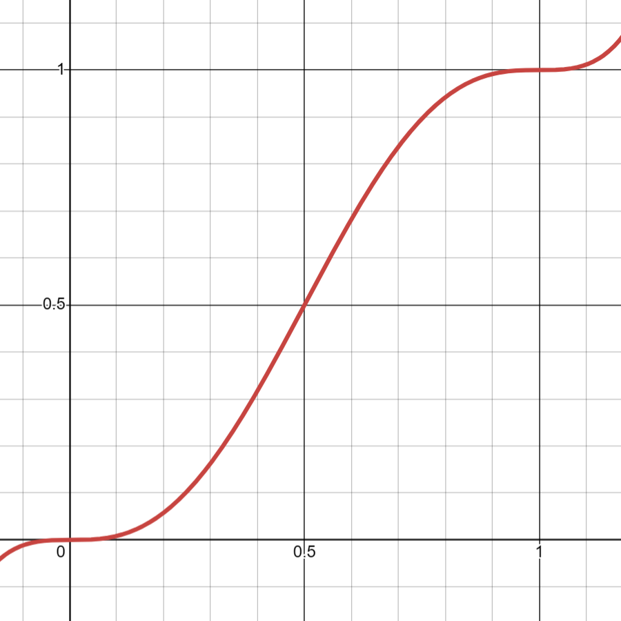
The key feature of this function is that its first and second derivatives are zero at both (x=0) and (x=1), which ensures a smooth transition across grid boundaries. This fade function is also vital in other noise algorithms like Value Noise and Simplex Noise.
GradFunction
private static float Grad(int hash, float x, float y)
{
    int h = hash & 7; // convert the hash to 0-7
    float u = h < 4 ? x : y;
    float v = h < 4 ? y : x;
    return ((h & 1) == 0 ? u : -u) + ((h & 2) == 0 ? v : -v);
}
The Grad function calculates the influence value (dot product). At first glance, it might be confusing. The principle described earlier involved assigning a random gradient vector and then calculating a dot product, but this function seems to have neither. In reality, it does calculate the influence, but in a simplified and optimized way.
If we expand the return values, the function is equivalent to this:
private static float Grad(int hash, float x, float y)
{
    int h = hash & 7; // convert the hash to 0-7
    switch (h)
    {
        case 0: return  x + y;
        case 1: return -x + y;
        case 2: return  x - y;
        case 3: return -x - y;
        case 4: return  y + x; // These are duplicates, but the original logic is more compact
        case 5: return -y + x;
        case 6: return  y - x;
        case 7: return -y - x;
        default: return 0;
    }
}
In the Grad function, hash represents the grid point. By pre-defining that the gradient vectors can only be one of (1, 1), (1, -1), (-1, 1), or (-1, -1), we can transform the dot product into simple additions and subtractions. This significantly improves performance and simplifies the code. The inputs x and y are the components of the distance vector from the grid point to the sample point. Thus, the final dot product simplifies to variations of x + y and x - y.
NoiseFunction
public static float GetNoise(float x, float y)
{
    // the grid cell coordinates
    int gridX = Floor(x) & 255;
    int gridY = Floor(y) & 255;
    // the relative coordinates of the point in the cell
    float dx = x - Floor(x);
    float dy = y - Floor(y);
    // fade the relative coordinates
    float u = Fade(dx);
    float v = Fade(dy);
    // hash coordinates of the 4 corners
    int hashA = Permutation512[gridX] + gridY;
    int hashB = Permutation512[gridX + 1] + gridY;
    // bilinear interpolation
    float y0 = Lerp(Grad(Permutation512[hashA], dx, dy), Grad(Permutation512[hashB], dx - 1, dy), u);
    float y1 = Lerp(Grad(Permutation512[hashA + 1], dx, dy - 1), Grad(Permutation512[hashB + 1], dx - 1, dy - 1), u);
    return Lerp(y0, y1, v);
}
Finally, the Noise function is the core of the algorithm, revealing how the calculations come together.
First, we use the Floor function to get the integer coordinates of the grid cell containing the point (x, y), which become gridX and gridY. These are used to look up the hash values for the four corner points of the cell: hashA, hashB, hashA+1, and hashB+1.
Next, we calculate dx and dy, which are the relative positions of the point within the grid cell (ranging from [0, 1)). These are then passed through the Fade function to get the smoothed interpolation weights u and v.
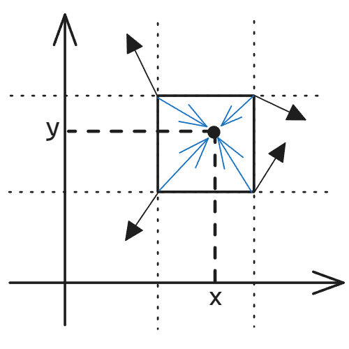
Finally, we calculate the Grad (influence) for each corner and use bilinear interpolation (Lerp) to blend them together, yielding the final noise value.
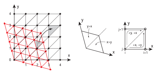
The diagram below clearly illustrates the relationships between these variables and the calculation of the influence values:
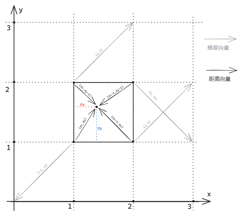
This concludes the discussion on the implementation of Perlin noise. Next, I will apply it to practical procedural generation.
2D Tilemap Generation
Now that we understand the principles of Perlin noise and have implemented the algorithm, let’s apply it to a practical scenario.
I have created several examples in Unity that use Perlin noise for procedural map generation, including 2D Tilemaps and 3D terrain. The project and code can be found in this GitHub repository:
https://github.com/hmxsqaq/Unity-ProceduralMapGenerationPerlinNoise
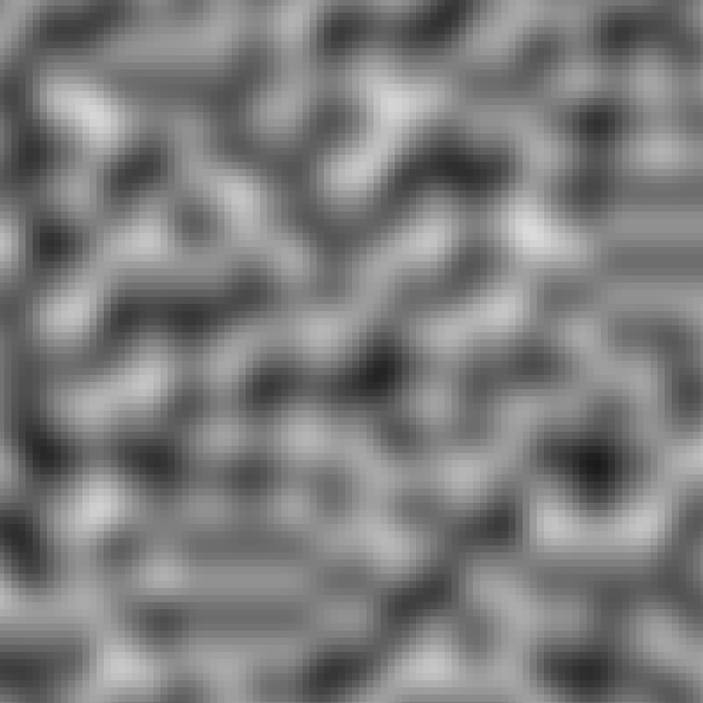
Generating a Noise Map
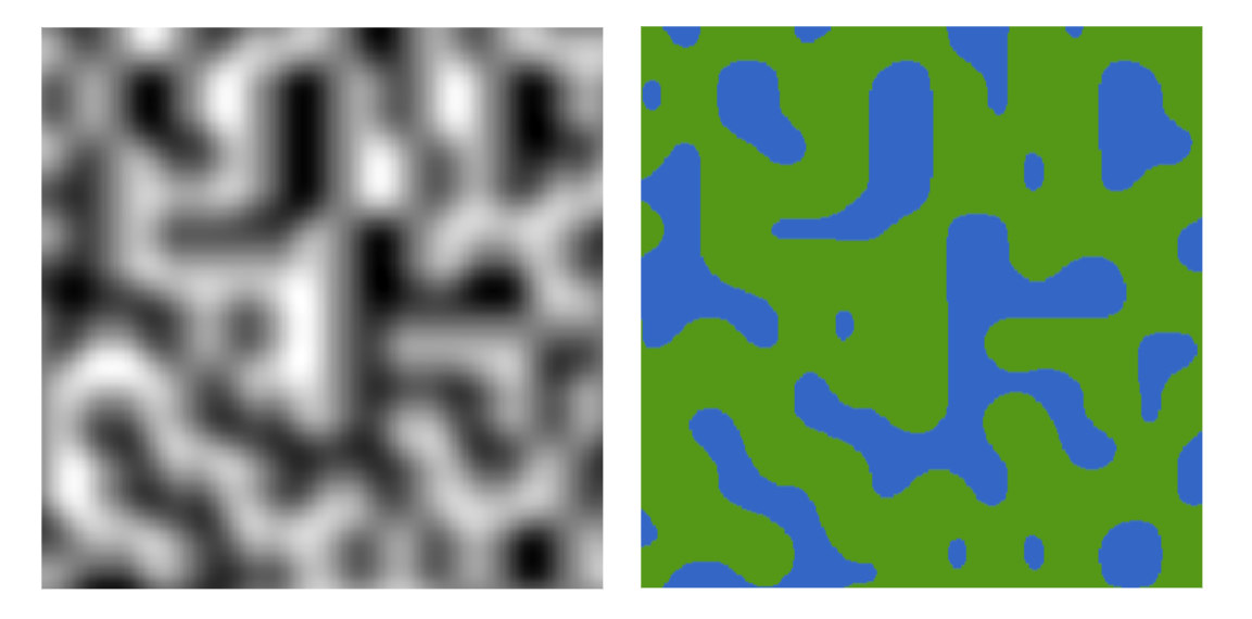
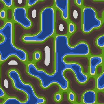
For 2D Tilemap generation, the application of Perlin noise is very direct. The noise map itself can be visualized as a 2D grayscale image, as shown below.
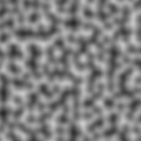
We just need to convert this 2D image into data and then map that data onto a Tilemap.
First, we need to generate the noise data. The following code accomplishes this:
public static float[,] GetNoiseMap(int seed, int width, int height, float scale)
{
    Random.InitState(seed);
    // init map
    float[,] noiseMap = new float[width, height];
    // avoid scale = 0;
    scale = scale <= 0 ? 0.0001f : scale;
    // get offset point
    Vector2 offset = new Vector2(Random.Range(-9999f, 9999f), Random.Range(-9999f, 9999));

    for (int y = 0; y < height; y++)
    {
        for (int x = 0; x < width; x++)
        {
            float sampleX = x / scale + offset.x;
            float sampleY = y / scale + offset.y;
            noiseMap[x, y] = PerlinNoise.GetNoise(sampleX, sampleY);
        }
    }
    return noiseMap;
}
In the code above, we first set a seed to ensure deterministic randomness. We use an offset and scale to sample the noise field and write the values into a 2D array noiseMap. The diagram below illustrates the concepts of offset and scale:
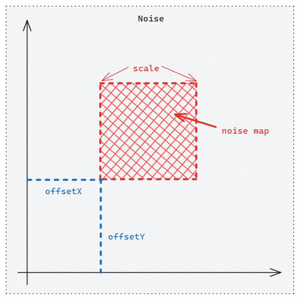
You can think of the Perlin noise function as an infinite noise texture. Our task is to sample a rectangular region from it. The offset determines the starting point of our sample, and it’s randomly generated. The scale determines the zoom level of our sample (more accurately, the “sampling frequency”). A smaller scale value results in a more detailed, zoomed-in noise map.
The following GIF effectively demonstrates the impact of scale on the noise map:
Generating the Tilemap
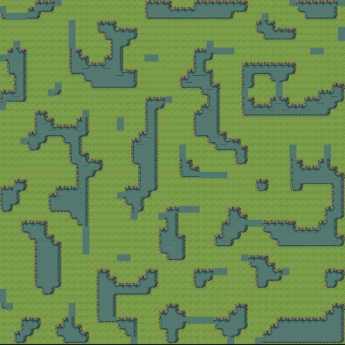
After obtaining the noise map, the next step is straightforward: map the data onto a Tilemap. I implemented this using both a grayscale visualization and a tile set from the internet (Overworld Tileset Grass Biome by beast-pixels). The GIF above shows the grayscale version, so I’ll showcase the tile-based one here.
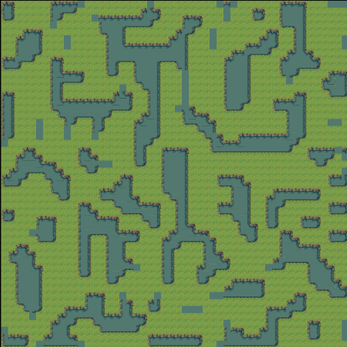
You can adjust the scale and waterProbability parameters to change the generated outcome.
Note that I used Unity’s Rule Tile feature to achieve adaptive tiling.
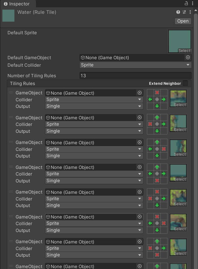
Improving the Generated Result
If we look closely at the generated terrain, we can spot some awkward areas:
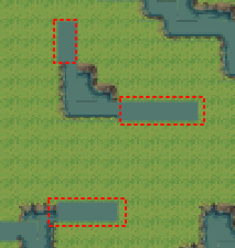
In the circled areas, the rule tiles are not matched correctly. This is because the tile set doesn’t provide corresponding tiles for these single-tile-wide “tendrils.” We can process the noise map to eliminate these unmatchable configurations.
A key characteristic of these areas is their thin, extended shape. We can simply iterate through each point and check its neighboring blocks.
private void EliminateSingleWater()
{
    while (true)
    {
        bool hasSingleWater = false;
        for (int w = 0; w < width; w++)
        {
            for (int h = 0; h < height; h++)
            {
                if (!(NoiseMap[w, h] < waterProbability) || !CheckAroundHavePairLand(w, h)) continue;
                NoiseMap[w, h] = 1; // Change to land
                hasSingleWater = true;
            }
        }
        if (!hasSingleWater) break;
    }
}

private bool CheckAroundHavePairLand(int x, int y)
{
    bool left = false, right = false, up = false, down = false;
    if (x > 0) left = NoiseMap[x - 1, y] > waterProbability;
    if (x < width - 1) right = NoiseMap[x + 1, y] > waterProbability;
    if (y > 0) up = NoiseMap[x, y - 1] > waterProbability;
    if (y < height - 1) down = NoiseMap[x, y + 1] > waterProbability;
    // A water tile is valid if it has land on opposite sides (left/right or up/down)
    return !( (left && right) || (up && down) ); // Correction: We want to eliminate tiles that DON'T have a pair of land neighbors
}
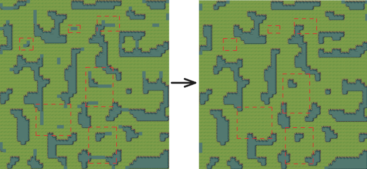
Correction from Author’s Logic: The original logic checked if a water tile had opposing land neighbors. To eliminate tendrils, we should remove water tiles that don’t have opposing land neighbors. The code here iteratively removes these undesirable water tiles. This adds some performance overhead but improves the final result’s quality.
Summary
In this exercise, I used a noise map and Unity’s Rule Tile to generate a random 2D Tilemap. I also implemented a cleanup step to remove tile configurations not supported by the rule set, resulting in a more polished map.
3D Mountain-like Terrain Generation
The above is a very basic application of Perlin noise, but it serves as an excellent starting point. In games like Minecraft, the use of noise is far more complex and integrated. They often employ multiple noise algorithms and generate several noise maps for different purposes. For instance, Minecraft uses multiple layers of fractal Perlin noise to generate maps for humidity, temperature, and biomes.
Next, I will explore more advanced applications of Perlin noise, starting from textures to create more realistic 3D mountainous terrain.
All the code used below can also be found in this GitHub repository:
https://github.com/hmxsqaq/Unity-ProceduralMapGenerationPerlinNoise
Heightmap Texture and Color Texture
When generating 3D mountainous terrain, we first need to create a color texture based on the noise map to shade the landscape.
The logic is very similar to the 2D Tilemap generation, but we replace the Tilemap with a Texture. The result is as follows:
By configuring a more detailed color gradient, we can achieve a better-looking terrain map.
Fractal Perlin Noise
We’ve used a multi-layered color map and Perlin noise to create a terrain map. It shows some random gradients, but the result isn’t very realistic—it’s too smooth and lacks detail. Our natural world is not so smooth. Fractal Perlin Noise can help solve this problem.
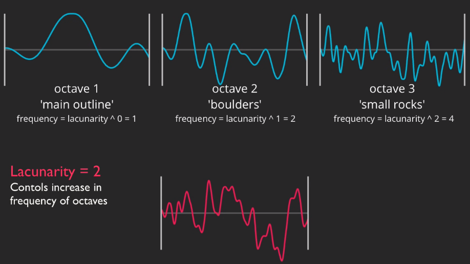
A fractal is a complex structure with self-similarity, meaning it looks similar at different scales. In nature, many phenomena (like mountains, coastlines, clouds) exhibit fractal characteristics. Fractal Perlin Noise combines Perlin noise with the concept of fractals. Specifically, it generates more complex and natural noise patterns by summing multiple layers of Perlin noise with different frequencies and amplitudes. This layering is often called “Octaves.” Each octave of Perlin noise has a different frequency and amplitude; the frequency is typically double the previous layer, and the amplitude is half. By summing multiple octaves, Fractal Perlin Noise can generate complex patterns with multi-scale detail.
We will introduce additional parameters into our noise map generation algorithm to implement this:
octaves: The number of noise layers, determining the level of detail.persistence: The factor by which the amplitude of each octave is reduced.lacunarity: The factor by which the frequency of each octave is increased.
My implementation is as follows:
public static float[,] GetNoiseMap(int seed, int width, int height, float scale, Vector2 offset,
                                   int octaves = 1, float persistance = 0.5f, float lacunarity = 2)
{
    Random.InitState(seed);
    // init map
    float[,] noiseMap = new float[width, height];
    // avoid scale <= 0
    scale = scale <= 0 ? 0.0001f : scale;
    // get offset point for each octave
    Vector2[] octavesOffsets = new Vector2[octaves];
    for (int i = 0; i < octaves; i++)
        octavesOffsets[i] = new Vector2(Random.Range(-9999f, 9999f), Random.Range(-9999f, 9999)) + offset;
    // store min and max value for normalization
    float minNoise = float.MaxValue;
    float maxNoise = float.MinValue;
    // store half width and height for sampling from the center
    float halfWidth = width / 2f;
    float halfHeight = height / 2f;

    for (int y = 0; y < height; y++)
    {
        for (int x = 0; x < width; x++)
        {
            float amplitude = 1;
            float frequency = 1;
            float noise = 0;

            for (int i = 0; i < octaves; i++)
            {
                float sampleX = (x - halfWidth) / scale * frequency + octavesOffsets[i].x;
                float sampleY = (y - halfHeight) / scale * frequency + octavesOffsets[i].y;
                float perlinNoise = PerlinNoise.GetNoise(sampleX, sampleY) * 2 - 1; // Range [-1, 1]
                noise += perlinNoise * amplitude;

                amplitude *= persistance;
                frequency *= lacunarity;
            }
            // get min and max noise value to normalize later
            if (noise < minNoise) minNoise = noise;
            if (noise > maxNoise) maxNoise = noise;
            noiseMap[x, y] = noise;
        }
    }

    // normalize the noise map to be in range [0, 1]
    for (int y = 0; y < height; y++)
        for (int x = 0; x < width; x++)
            noiseMap[x, y] = Mathf.InverseLerp(minNoise, maxNoise, noiseMap[x, y]);

    return noiseMap;
}
This implementation iteratively adds layers of noise, providing several parameters for adjustment, such as octaves, persistence, lacunarity, and offset. By tweaking these, we can generate a wide variety of noise textures.
The GIF below shows the effect:
With fractal Perlin noise, the quality of the terrain map has significantly improved. It has richer detail and more varied layers:
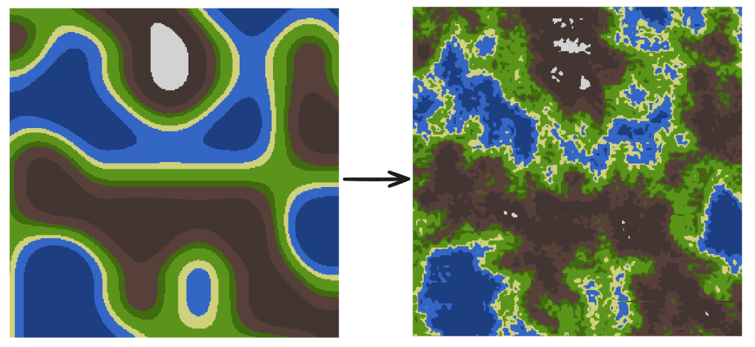
Furthermore, by adjusting the parameters, we can achieve different terrain styles:
Giving the Terrain Height
In the previous steps, I applied a color texture to a plane based on the noise map. Now, let’s give it height to turn it into a true mountain landscape.
The idea is simple: we already have a heightmap (our noise map). We can use it to set the vertex heights of a plane’s mesh.
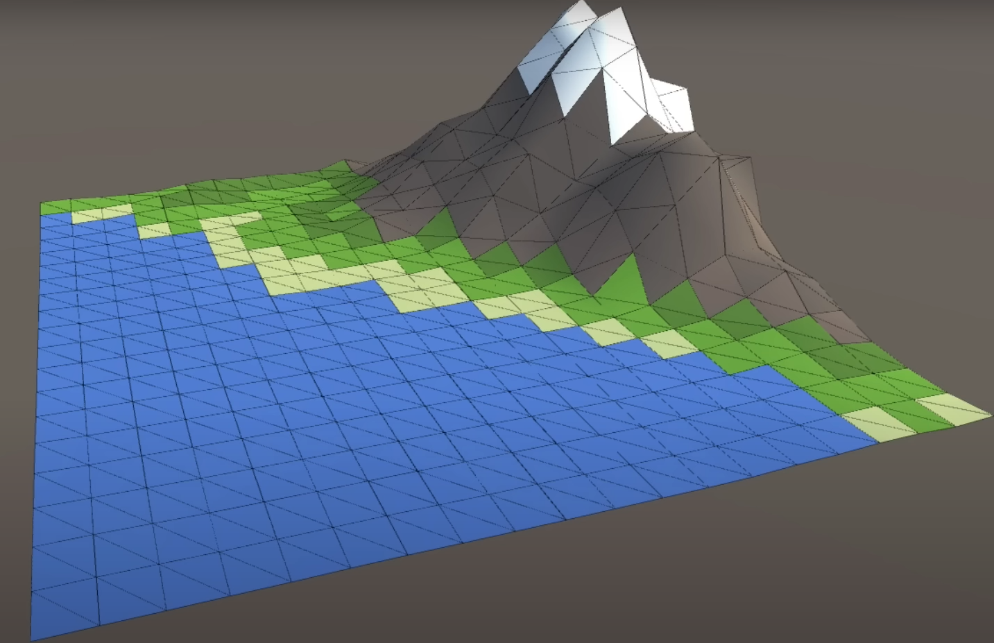
As shown in the code below, I generate the mesh data based on the noise map:
private static Mesh GenerateTerrainMesh(float[,] noiseMap, float heightMultiplier, AnimationCurve heightCurve)
{
    int width = noiseMap.GetLength(0);
    int height = noiseMap.GetLength(1);
    // get offset to center the mesh
    float topLeftX = (width - 1) / -2f;
    float topLeftZ = (height - 1) / 2f;

    MeshData meshData = new MeshData(width, height);
    int vertexIndex = 0;
    for (int y = 0; y < height; y++)
    {
        for (int x = 0; x < width; x++)
        {
            meshData.Vertices[vertexIndex] = new Vector3(topLeftX + x, heightCurve.Evaluate(noiseMap[x, y]) * heightMultiplier, topLeftZ - y);
            meshData.UVs[vertexIndex] = new Vector2(x / (float)width, y / (float)height);
            if (x < width - 1 && y < height - 1)
            {
                meshData.AddTriangle(vertexIndex, vertexIndex + width + 1, vertexIndex + width);
                meshData.AddTriangle(vertexIndex + width + 1, vertexIndex, vertexIndex + 1);
            }
            vertexIndex++;
        }
    }
    return meshData.CreateMesh();
}
I also added heightMultiplier and heightCurve parameters. These control the overall height scale and the height distribution curve, respectively, allowing for finer control over the terrain’s shape. For example, we can use the heightCurve to map all noise values from 0 to 0.4 to a height of 0, ensuring a flat sea level.
The resulting effect is as follows:
Other Procedural Generation Algorithms
Besides basic Perlin noise, many other algorithms are widely used in procedural terrain generation. This section will briefly introduce three of them: Simplex Noise, DLA, and Hydraulic Erosion.
Simplex Noise
Simplex Noise, also invented by Ken Perlin in 2001, is an improved noise function designed to overcome some of the shortcomings of classic Perlin noise.
Simplex noise has several notable features:
- Higher Computational Efficiency: As the number of dimensions increases, the number of gradient vectors Perlin noise needs to calculate grows exponentially, making its performance in higher dimensions unacceptable. Simplex noise has a much lower computational complexity in higher dimensions, making it more advantageous for real-time applications.
- Better Visual Quality: Simplex noise does not produce the noticeable axis-aligned artifacts that can appear in Perlin noise, resulting in more natural and realistic terrain.
- Better Gradient Distribution: The gradient distribution of Simplex noise is more uniform, which helps create smoothly transitioning terrain.
The specific implementation of Simplex noise is relatively complex and won’t be detailed here, but you can refer to this paper for an implementation. Its core idea involves dividing the input space into a series of simplices (like triangles or tetrahedra) and generating random gradients at their vertices. The final noise value is then generated by interpolating these gradients.
DLA Algorithm
DLA (Diffusion-Limited Aggregation) is an aggregation model based on random walks. It was first proposed by T.A. Witten and L.M. Sander in 1981 to simulate aggregation phenomena in nature, such as electrodeposition, crystal growth, and urban sprawl.
The basic idea is to start with an initial seed and have randomly walking particles attach to the aggregate, forming complex fractal structures. The steps are:
- Initialization: Place a seed particle in space.
- Particle Generation: Randomly generate a new particle at the boundary of the space.
- Random Walk: The particle performs a random walk until it is adjacent to the aggregate.
- Attachment: The particle sticks to the aggregate and becomes part of it.
- Repeat: Repeat steps 2-4 until the desired structure is formed.
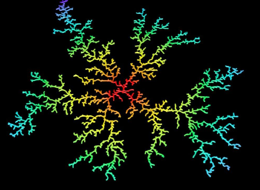
The DLA algorithm is excellent at generating tree-like or branching structures like the one above. By assigning height based on the structure’s density and applying some blurring, it can be used to form the underlying structure of mountain ranges. However, DLA is iterative and computationally expensive. Its nature makes it difficult to parallelize on a GPU, which limits its application.
Hydraulic Erosion Algorithm
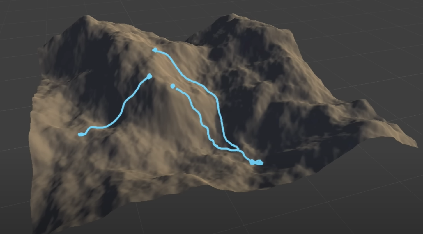
This is an algorithm that attempts to simulate natural processes. In the formation of natural terrain, erosion plays a crucial role and has a significant impact. By simulating these processes, we can generate terrain with higher detail and realism.
Hydraulic erosion simulates the erosion and deposition caused by rainfall and rivers. The basic steps are:
- Rainfall: Distribute rainfall randomly across the terrain.
- Water Flow Path: Simulate the path of water flow, calculating the water volume at each point.
- Erosion and Deposition: Based on water flow and terrain slope, calculate the amount of erosion and deposition at each point and update the terrain height.
For an implementation reference, see this repository.
Erosion algorithms also have their drawbacks. Since erosion is a post-processing step, it means the terrain generated by Perlin noise loses its deterministic (hashable) property. Additionally, being an iterative process, it incurs a significant performance cost.